Mobile Training and Mounting Steps
This guide outlines the Mobile training and mounting steps necessary for different profiles used in ZeroKey’s system for positioning and orientation. The training process is a critical step that must be repeated each time a new navigation run is started. Detailed instructions are provided for Pedestrian, Tooltip, Hybrid AGV and AGV, and Generic profiles.
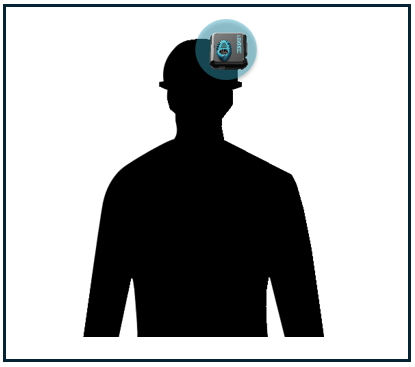
When mounting the Mobile to the asset you wish to track, ensure that the Mobile’s transducer has maximum visibility to the Anchors and can maintain a clear line of sight to at least four Anchors at all times during both the training and navigation processes. This should be applied in all profiles to obtain accurate Mobile position and orientation.
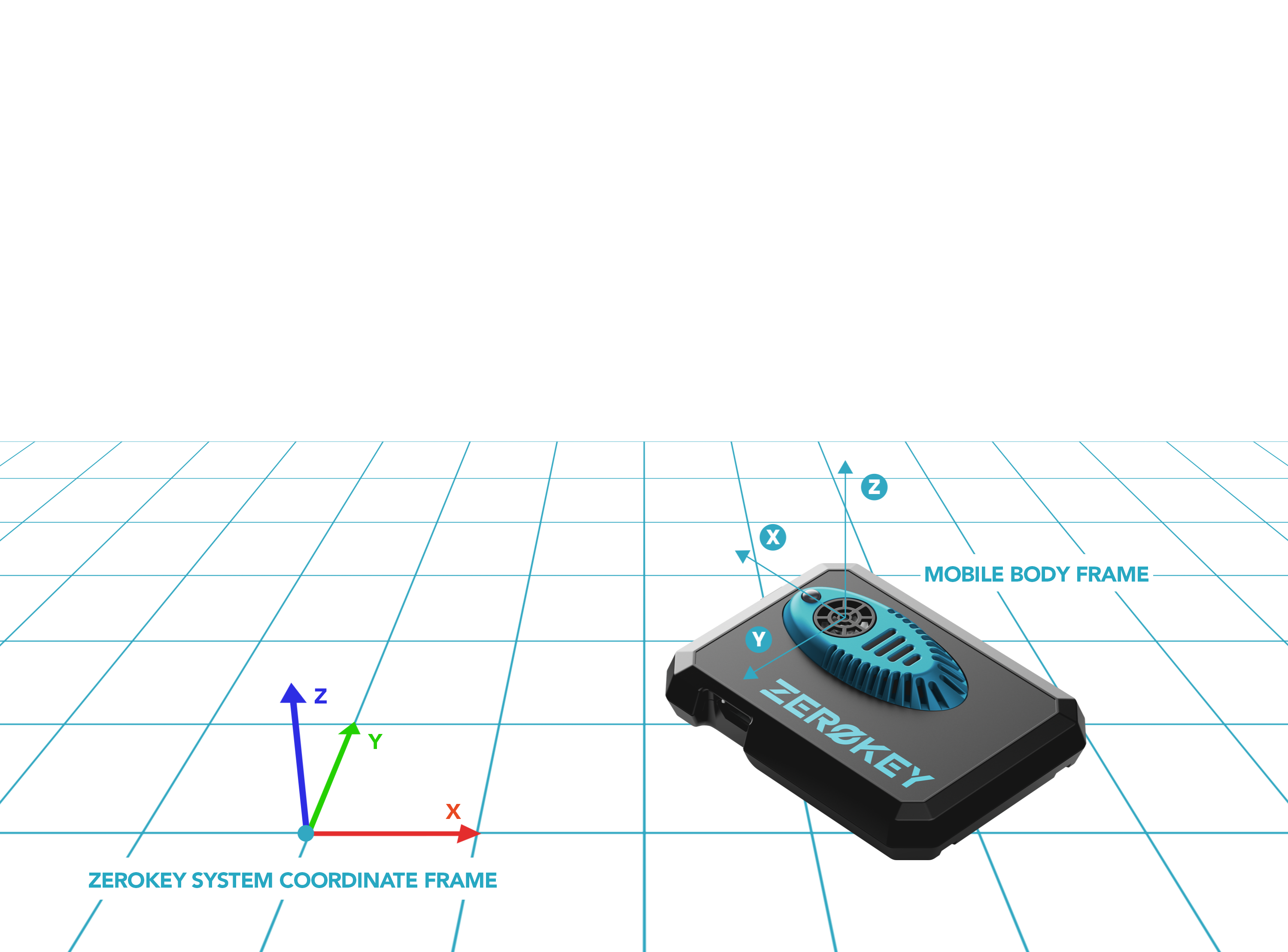
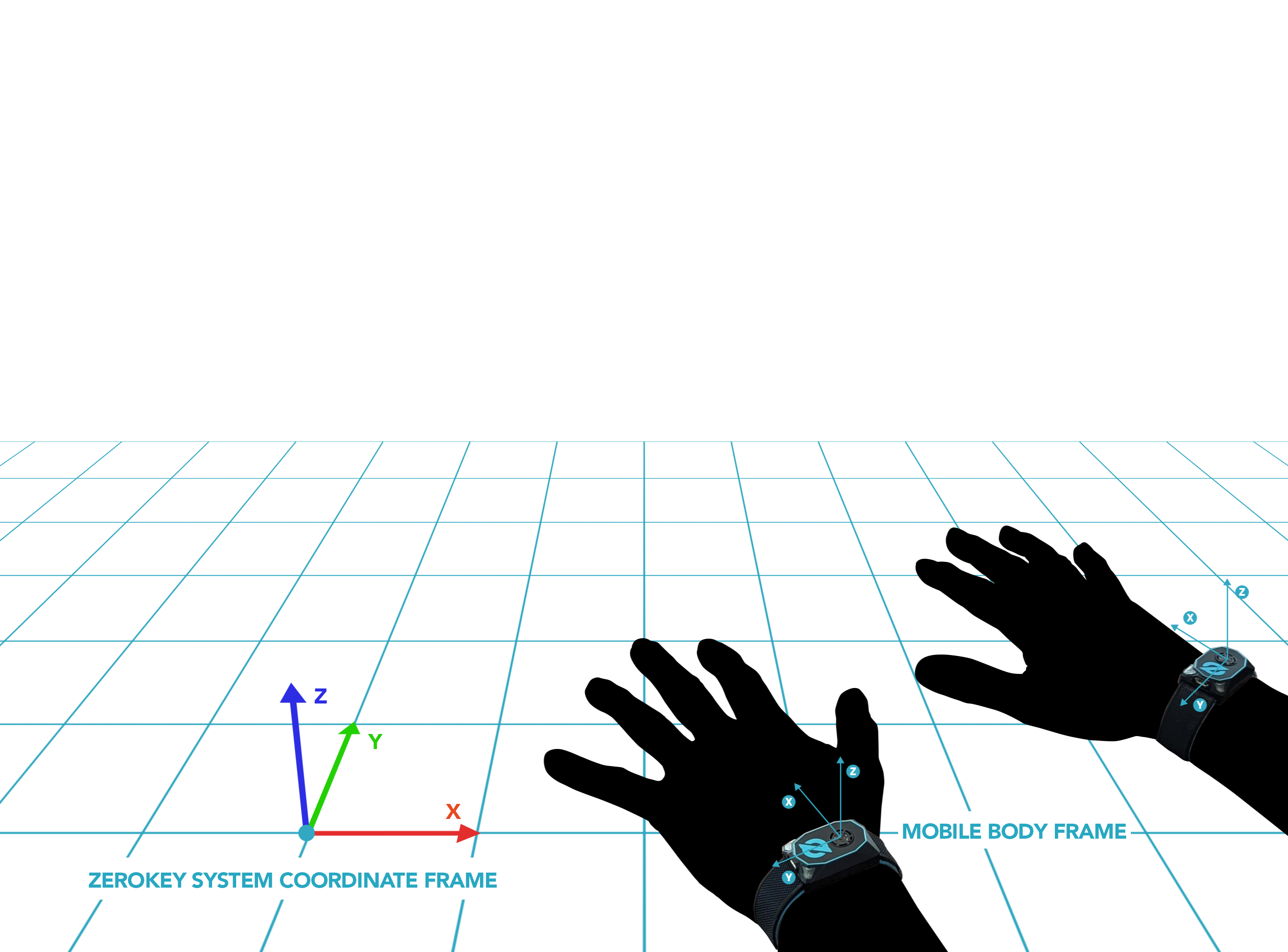
For more information on the Mobile Body Frame in the context of ZeroKey’s Quantum RTLS, visit our help article Changes in the Mobile Body Frame from Quantum RTLS 1.0 to 2.0.
The body frame of a Mobile refers to a coordinate system that is fixed to the Mobile, moving and rotating along with it. This frame is used as a reference point to describe the device’s orientation relative to another global or local frame, such as the ZeroKey Quantum RTLS frame. Orientation parameters, including roll, pitch, and yaw, are defined using this body frame.


Pedestrian Mode
Mounting: The Mobile should be mounted flat with the transducer facing up.
Training: Perform 1-2 laps at a normal walking speed, ensuring that the Mobile’s transducer maintains a clear line of sight to a minimum of at least four Anchors at all times.

Tooltip Mode
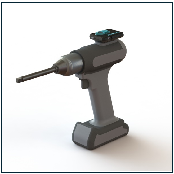
Mounting: The Mobile should be mounted on top of where the tooltip will extend from. The image below displays how a Mobile can be mounted on a power drill.

Ensure the mounting is rigid and includes insulation between the Mobile and the tool to minimize the effect of noise and vibrations on the navigation performance. The Mobile should be mounted on the tool in a position that ensures maximum visibility to the Anchors throughout the workflow. To calculate accurate positions, the Mobile needs a clear line of sight to at least four Anchors.
Training:
Before starting positioning, hold the Mobile stationary and level within the tracked space. Ensure that it has a clear line of sight to at least four Anchors.
Start positioning.
Move the Mobile forward by hand, with the button facing in the forward direction at a moderate speed (>0.25m/s) for at least 0.5 meters. The INS flags in the log will transition to
4: Successful fused positioning and orientation. In the Gateway log,pf:##will be seen with every position update line. The first#is the INS flag and the second#is the ultrasonic flag. At this point, the heading should point in the correct direction.
08/16/2024 17:20:17: |I| rf_cmd_update_position: Node: CD:F8:B8:66:5D:3C seq: 359696 ins: 0 pos: -0.64693,-1.78074,-0.66763 vel: 0.05126,0.00339,0.00082 rot: 0.69107,0.15448,0.12433,0.69506 flag: 00 pf: 43 ts: 7729537 toffset: 129470
Next, move the Mobile in a forward and reverse motion by hand, ensuring no angular motion. The heading should point in the correct direction with no drift. Flag 4 should still be reporting in the log. If drift is observed or the heading is incorrect, reboot the Mobile by briefly pressing the grey button and restart from Step 3.
Hybrid AGV and AGV Mode
Mounting: The Mobile should be mounted flat on the AGV with the button facing forward. Ensure the mounting is rigid and includes isolation between the Mobile and the AGV to minimize the effect of noise and vibrations on the navigation performance.
Training:
When positioning starts, the first motion should be forward and straight, with a speed greater than 0.3m/s for 5 seconds.
After this, the AGV can proceed with its designated trajectory or expected route. Training will be live during the AGV navigation. It is recommended to include additional motions in the AGV trajectory (i.e., rotations) after the initial forward motion to ensure accurate training.
Generic Profile
This profile is less restricted, offering flexibility for use cases that don’t have the specific requirements of the previous three profiles. However, for better accuracy, it is advised to use one of the specialized profiles if applicable.
Mounting and Training: Follow the mounting and training steps that closely resemble the applicable profile. The first motion should adhere to the initial motion requirements for the AGV case outlined above.
