Creating a device map is essential for documenting Gateway and Anchor MAC addresses along with their precise locations within the tracked space. This map serves as a valuable reference during calibration and for managing device locations or replacements.
The MAC address can be found on the label on the back of each Gateway and Anchor. Use a handheld scanner to scan the QR code on each device to quickly enter information into an Excel spreadsheet.
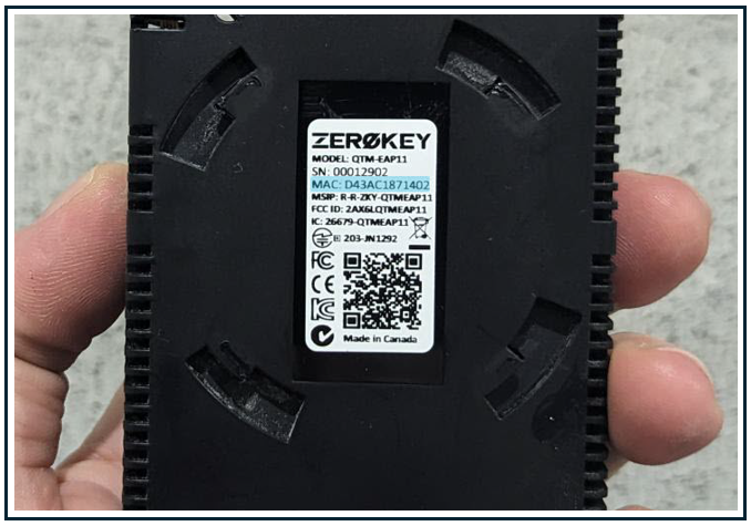
Once scanned, the device’s MAC address can be found in a line of text that also includes the product SKU, serial number, and date of manufacture. The output will appear as a single line of text, like this: QTMUMR101000002103DECD05A8665012302021
To determine the MAC address, divide the text into sections:
-
Product SKU: QTMUMR10
-
Serial number: 00002103
-
MAC address: DECD05A86650
-
Date of manufacture: 12302021
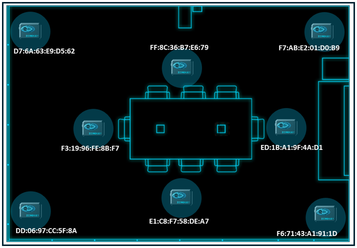
The following is a simple device map for a ZeroKey starter kit that is set up in a small boardroom. The Gateway is excluded in this mapping. When deploying a starter kit or a small-scale test system, marking the Gateway location may not be necessary. However, marking the Anchor locations in detail is beneficial, as the user may rely on the device map for assistance during calibration.
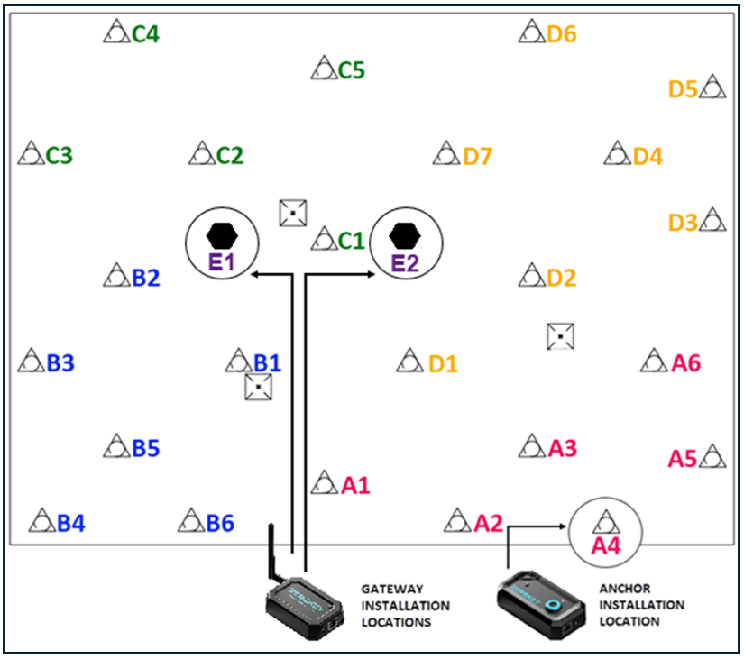
The following is an example of a large-scale device map, complete with both Anchor and Gateway locations.
The following table organizes each device with its corresponding MAC address.
|
Anchor # |
Anchor MAC |
|
Anchor # |
Anchor MAC |
|
A1 |
D8:DD:D0:20:E0:C5 |
|
C1 |
CC:AE:05:04:CC:71 |
|
A2 |
D5:6F:EF:65:47:43 |
|
C2 |
EC:73:28:AC:A3:8D |
|
A3 |
C0:A2:C1:48:27:DE |
|
C3 |
F8:85:3F:4D:21:9C |
|
A4 |
C1:84:22:C0:84:AD |
|
C4 |
EB:88:42:61:05:78 |
|
A5 |
EC:0F:D2:A7:57:A6 |
|
C5 |
FE:12:40:63:B8:37 |
|
A6 |
D5:EC:72:C3:A1:74 |
|
D1 |
D6:36:08:47:B7:A4 |
|
B1 |
F8:5B:19:F8:1A:78 |
|
D2 |
F5:D5:08:C1:40:0F |
|
B2 |
E3:52:0A:70:B4:FF |
|
D3 |
C0:24:43:29:BE:A8 |
|
B3 |
C6:55:02:0B:E1:5B |
|
D4 |
DB:97:B6:5B:07:8F |
|
B4 |
F0:81:A9:8E:D5:ED |
|
D5 |
E2:52:F8:5A:D9:74 |
|
B5 |
F3:9F:45:EF:C2:97 |
|
D6 |
E9:4C:0E:84:1D:81 |
|
B6 |
D0:A8:FB:FE:D7:D6 |
|
D7 |
E9:E8:F3:DD:A2:BE |
|
E1 |
E4:F5:43:14:AD:C8 |
|
E2 |
F6:6C:53:8D:B1:E1 |
Creating a device map offers several key benefits: it simplifies the calibration process by making it easy to locate Anchors needing additional data, facilitates quick identification of device locations for hardware swaps, and provides valuable reference information for evaluating positioning logs or system data. Additionally, it serves as a basic visual aid for determining Anchor density requirements.